Monday 29 April 2013

Remove “Windows Experience Index Rating” Link from Windows 7 System Properties?

Microsoft introduced WEI (Windows Experience Index) rating in Windows Vista which calculates and rates your Computer system based on the hardware you have in your computer. This rating score is displayed in System Properties window as shown in following screenshot:


In this tutorial, we'll tell you how to remove "Windows Experience Index" rating link from Windows 7 System Properties. We have tested this method in Windows 7 only but it should also work in Windows Vista and Windows 8.
1. First go to "%windir%\System32\" folder and copy systemcpl.dll file to some other location for example Desktop.
Here %windir% represents "Windows" directory which can be found in the system drive where Windows is installed. In most of the cases its C:\Windows.
2. Now open the new file in Resource Hacker and go to following key:

Click here to Download Resource Hacker 
UIFILE -> 1001
3. In right-side pane , you'll need to delete lines 158 to 170 to remove Windows Experience Index rating link:
<element id="atom(RatingInfo)" layoutpos="top" layout="rowlayout(171)" padding="rect(0rp,0rp,0rp,7rp)">
<element content="resstr(1543)" width="150rp"/>
<element layout="borderlayout()">
<element id="atom(RatingImage)" margin="rect(0rp,0rp,3rp,0rp)" layoutpos="none" content="" accessible="true" accrole="graphic" accname="resstr(304)"/>
<element id="atom(RatingInformation)" contentalign="middleleft" layout="borderlayout()" layoutpos="client">
<element layout="flowlayout(0,2)" layoutpos="left" accessible="false">
<NavigateButton layoutpos="left" layout="borderlayout()" navigationtargetroot="Microsoft.PerformanceInformationAndTools">
<button id="atom(RatingText)" active="mouse|keyboard" layoutpos="left" content="resstr(1544)"/>
</NavigateButton>
</element>
</element>
</element>
</element>


4. After deleting the lines, click on "Compile Script" button.
5. That's it. Now save the file.
6. Now we'll need to replace original systemcpl.dll file present  in "C:\Windows\System32\" folder with our new systemcpl.dll file which we saved at Desktop or some other location.

7 a. First take ownership of "C:\Windows\System32\systemcpl.dll" file using following tutorial:

Add Take Ownership Option in File / Folder Context Menu in Windows 

7 b. Now rename it to "systemcpl_backup.dll" or any other name.
7 c. Now copy your new modified "systemcpl.dll" file from Desktop to "System32" folder.
8. That's it. Now check System Properties again and it'll no longer show Windows Experience Index rating score and link. No need to restart or log off.


Add “Take Ownership” Option in Files and Folders Context Menu in Windows


Many times you need to take ownership of a file or folder in Windows. For example, when you want to customize Windows UI and need to replace existing system files with a new one.
You have to follow no. of steps to take ownership and grant yourself full permission to access the file or folder. But now you can do it in a single step.

You just need to download following zip file and extract it. You'll get a .REG file. Run the file and accept the confirmation:

Download Here

It'll add an extra option "Take ownership" in file and folder context menu:


Now you can right-click on any file or folder and select "Take ownership" option. It'll make you the owner of the file or folder and you can perform your desired operation on that file or folder.


Open Command Prompt as Administrator always


If you want to always open Command Prompt window as Administrator, you can follow these simple steps:

  1. Create a shortcut of Command prompt on Desktop.
  2. Right-click on Command Prompt shortcut and select Properties.
  3. Now click on "Advanced" button present in "Shortcut" tab.
  4. Enable "Run as administrator" option and apply the changes.
  5. That's it. Now Command Prompt window will always open with Administrator privileges.


Restore Missing “Desktop (create shortcut)” Item in Send To Menu in Windows XP, Vista and 7


A few people asked solution of this frequently occurring problem, so today I decided to post a simple and detailed solution of this problem.
As we all know about "Send To" menu which appears when we right-click on a file or folder in Windows Explorer. It contains some useful items like "Desktop (create shortcut)" which can create a shortcut of the selected file/folder on Desktop within a few seconds. Its really a useful option.


But sometimes this item gets deleted from "Send To" menu accidentally or intentionally. Following tutorial will help you in restoring this useful item back in "Send To" menu:


METHOD A:
1. Type "shell:sendto" in RUN dialog box and press Enter. It'll open "Send To" folder.
2. Now right-click on blank area in the folder and select "New -> Text document". It'll create a text file with the name "New Text Document.txt". Rename this file and set its name to "Desktop (create shortcut)"..DeskLink
3. That's it. Now you'll get "Desktop (create shortcut)" option back in "Send To" menu.


NOTE: Make sure "Hide extensions for known file types" option is disabled in "Folder Options", otherwise the second step might not work and the text file will not convert in desktop shortcut item.


METHOD B:
This method will only work in Windows XP. It'll not work in Vista and 7:
1. Type following command in RUN dialog box:
regsvr32 sendmail.dll
2. It'll re-create the missing "Desktop (create shortcut) option in "Send To" menu.


METHOD C:
This is the simplest method. Just download following zip file, extract it and copy the extracted file to "Send To" folder:


desktop-create-shortcut


Saturday 27 April 2013

OSI Model: Understanding the Seven Layers of Computer Networks


Introduction

The Open Systems Interconnection (OSI) model is a reference tool for understanding data communications between any two networked systems. It divides the communications processes into seven layers. Each layer both performs specific functions to support the layers above it and offers services to the layers below it. The three lowest layers focus on passing traffic through the network to an end system. The top four layers come into play in the end system to complete the process.


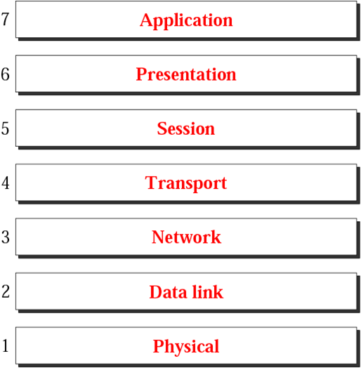
Seven Layers/Standards of the OSI Model :-


Layer 1 - Physical Layer :


Application
Presentation
Session
Transport
Network
Data Link
Physical 
The physical layer, the lowest layer of the OSI model, is concerned with the transmission and reception of the unstructured raw bit stream over a physical medium. The physical layer of the OSI model defines connector and interface specifications, as well as the medium (cable) requirements. Electrical, mechanical, functional, and procedural specifications are provided for sending a bit stream on a computer network. 

The Physical Layer receives data from the data link Layer, and transmits it to the wire. The physical layer controls the electrical and mechanical functions related to the transmission and receipt of a communications signal. It also manages the encoding and decoding of data contained within the modulated signal. 


Note that for two devices to communicate, they must beconnected to the same       type of physical medium (wiring). 802.3 Ethernet to 802.3 Ethernet, FDDI to FDDI, serial to serial etc. Two end stations using different protocols can only communicate through a multi-protocol bridge or a router.
The physical layer is responsible for:
  1. Communication with the data link layer above it.
  2. Fragmentation of data into frames.
  3. Reassembly of frames into data link Protocol Data Units.
  4. Transmission to the physical media.
  5. Receiving from the physical media.
Protocols :-
IEEE 802
IEEE 802.2
ISO 2110
ISDN


Layer 2 - Data Link Layer :


Application
Presentation
Session
Transport
Network
Data Link
Physical


The data link Layer is the second layer of the OSI model. Data link layers handle data transfer between network layer and physical layer. It receive data from network layer, adds header and trailer to the data and passes data to physical layer . At the receiver, it receiver data from the physical layer removes the header and trailer and passes the data to the network layer.


The data link layer performs various functions depending upon the hardware protocol used, but has four primary functions:

  1. COMMUNICATION with the Network layer above.
  2. SEGMENTATION of upper layer datagrams (also called packets) into frames in sizes that can be handled by the communications hardware.
  3. BIT ORDERING. The data link layer organizes the pattern of data bits into framesbefore transmission. The frame formatting issues such as stop and start bits, bit order, parity and other functions are handled here. Management of big-endian / little-endian issues are also managed at this layer.
  4. COMMUNICATION with the Physical layer below
  5. Handles data frames between the Network and Physical layers.
  6. Frame traffic control: tells the transmitting node to "back-off" when no frame buffers are available.
  7. Frame sequencing: transmits/receives frames sequentially.
  8. Frame acknowledgment: provides/expects frame acknowledgments. Detects and recovers from errors that occur in the physical layer by retransmitting non-acknowledged frames and handling duplicate frame receipt. 


        This layer provides reliable transit of data across a physical link. The data link layer is concerned with physical addressing, network topology, physical link management, error notification, ordered delivery of frames, and flow control.

        Protocols :
        a) Logical Link Control (LLC)
        i. Error correction and flow control
        ii. Manages link control 


        b) Media Access Control (MAC)
        i. Communicates with the adapter card.
        ii. Controls the type of media being used.


        NOTE: The data link layer is responsible for moving frames from one hop (node) to the next.


        Layer 3 - Network Layer :


        Application
        Presentation
        Session
        Transport
        Network
        Data Link
        Physical
        Network layer is the 3rd layer of the OSI model. The data unit at this layer is known as packet. The network layer is not needed if the two communicating lie in same network. However, when the two devices are on the different network,  network layer  is essential for the source to destination delivery of packets.


        This layer provides switching and routing technologies, creating logical paths, known as virtual circuits, for transmitting data from node to node. Routing and forwarding are functions of this layer, as well as addressing, inter-networking,  error handling, congestion control and packet sequencing.


        IP (Internet Protocol) is responsible for routing, directing datagrams from one network to another. The network layer may have to break large datagrams, larger than MTU, into smaller packets and host receiving the packet will have to reassemble the fragmented datagram. The Internetwork Protocol identifies each host with a 32-bit IP address. IP addresses are written as four dot-separated decimal numbers between 0 and 255, e.g., 129.79.16.40. The leading 1-3 bytes of the IP identify the network and the remaining bytes identifies the host on that network. The network portion of the IP is assigned by InterNIC Registration Services, under the contract to the National Science Foundation, and the host portion of the IP is assigned by the local network administrators. For large sites, the first two bytes represents the network portion of the IP, and the third and fourth bytes identify the subnet and host respectively. Even though IP packets are addressed using IP addresses, hardware addresses must be used to actually transport data from one host to another. The Address Resolution Protocol (ARP) is used to map the IP address to it hardware address.

        Functions :

        1. Translates logical network address and names to their physical address (e.g. computername ==> MAC address).
        2. Responsible for addressing, determining routes for sending and managing network problems such as packet switching, data congestion and routing.
        3. If router can’t send data frame as large as the source computer sends, the network layer compensates by breaking the data into smaller units. At the receiving end, the network layer reassembles the data.
        Protocols :-
        IP
        ARP
        RARP
        ICMP
        RIP
        OSFP
        IGMP
        IPX
        NWLink
        NetBEUI
        OSI
        DDP
        DECnet


        Note : The network layer is responsible for the delivery of individual packets from the source host to the destination host.


        Layer 4 - Transport Layer :


        Application
        Presentation
        Session
        Transport 
        Network
        Data Link
        Physical


        Transport layer is the 4th layer of the OSI model. The data unit at this layer is known as Segment. Transport layer offers end-to-end communication between devices through a network. depending on the application, the transport layer either offers reliable, connection-oriented or connectionless, best-effort communications.

        Two transport layer protocols:
        1. Transmission Control Protocol (TCP),
        2. User Datagram Protocol (UDP)

        At the transport layer. Reliability and speed are the primary difference between these two protocols.
         TCP establishes connections between two hosts on the network through 'sockets' which are determined by the IP address and port number. TCP keeps track of the packet delivery order and the packets that must be resent. Maintaining this information for each connection makes TCP a stateful protocol. 
        UDP on the other hand provides a low overhead transmission service, but with less error checking. NFS is built on top of UDP because of its speed.


        Functions :

        1. Communicate with the Session layer above.
        2. Reassemble transport Protocol Data Units into data streams
        3. Reliable protocols operating at this layer will
          • Detect errors and lost data
          • Recover lost data
          • Manage retransmission of data.
        4. Segmentation of data streams into transport Protocol Data Units.
        5. Communicate with the Network layer below.
        Protocols :
        TCP
        ARP
        RARP
        SPX
        NWLink
        NetBIOS / NetBEUI
        ATP
        UDP
        DCCP

        NoteThe transport layer is responsible for the delivery of a message from one process to another.


         Layer 5 - Session Layer :


        Application
        Presentation
        Session
        Transport
        Network
        Data Link
        Physical

        Session layer is the 5th layer of the OSI model. The session layer allows session establishment between processes running on different stations. This layer establishes, manages and terminates connections between applications. The session layer sets up, coordinates, and terminates conversations, exchanges, and dialogues between the applications at each end.


        The session layer tracks connections, also called sessions. The session layer should keep track of multiple file downloads requested by a particiular FTP application, or multiple telnet connections from a single terminal client, or web page retrievals from a web server.
        With TCP/IP this functionality is handled by application software addressing a connection to a remote machine and using a different local port number for each connection.


        Functions :

        1. Session establishment, maintenance and termination: allows two application processes on different machines to establish, use and terminate a connection, called a session.
        2. Session support: performs the functions that allow these processes to communicate over the network, performing security, name recognition, logging, and so on. 
        Protocols :
        NetBIOS
        Names Pipes
        Mail Slots
        RPC
        SAP
        L2TP
        PPTP
        SPDY


        Layer 6 - Presentation Layer :

        Application
        Presentation
        Session
        Transport
        Network
        Data Link
        Physical


        Presentation layer is the 6th layer of the OSI model. The presentation layer handles the conversion of data between a Standards-based or platform independant formats to a format understood by the local machine. This allows for data to be transported between devices and still be understood.


        The presentation layer provides:
        1. Character code translation: for example, ASCII to EBCDIC.
        2. Data conversion: bit order, CR-CR/LF, integer-floating point, and so on.
        3. Data compression: reduces the number of bits that need to be transmitted on the network.
        4. Data encryption: encrypt data for security purposes. For example, password encryption. 

        Protocols :
        MIME
        XDR
        TLS
        SSL


        Layer 7 - Application Layer :


        Application
        Presentation
        Session
        Transport
        Network
        Data Link
        Physical


        The OSI model defines the application layer as being the user interface. The OSI application layer is responsible for displaying data and images to the user in a human-recognizable format and to interface with the presentation layer below it.


        Examples of applications that utilize the network are:

        1. Telnet
        2. FTP
        3. Instant Message software (AIM, MSN, ICQ, Yahoo)
        4. Microsoft Windows File Shares
        5. Web Browsers (Internet Explorer, Firefox, Google Chrome, Safari)


        Protocols :
        FTAM
        DNS
        FTP
        TFTP
        BOOTP
        SNMP
        RLOGIN
        SMTP
        MIME
        NFS
        FINGER
        TELNET
        NCP
        APPC
        AFP
        SMB


        Quick View at the Functions of the layers 


        OSI Model and Protocol


        Network Communications through the OSI Model :


        Network Communications through the OSI Model. Some info. is added at every layer into the data known as "HEADERS"


        The figure represents two networked computers. They are running identical operating systems and applications and are using identical protocols (or rules) at all OSI layers. Working in conjunction, the applications, the OS, and the hardware implement the seven functions described in the OSI model.

        Each computer is also running an e-mail program that is independent of the OSI layers. The e-mail program enables the users of the two computers to exchange messages. Our figure represents the transmission of one brief message from Sam to Charlie.

        The transmission starts when Sam types in a message to Charlie and presses the "send" key. Sam's operating system appends to the message (or "encapsulates") a set of application-layer instructions (OSI Layer 7) that will be read and executed by the application layer on Charlie's computer. The message with its Layer 7 header is then transferred to the part of the operating system that deals with presentation issues (OSI Layer 6) where a Layer 6 header is appended to the message. The process repeats through all the layers until each layer has appended a header. The headers function as an escort for the message so that it can successfully negotiate the software and hardware in the network and arrive intact at its destination.

        When the data-link-layer header is added at Layer 2, the data unit is known as a "frame." The final header, the physical-layer header (OSI Layer 1) tells the hardware in Sam's computer the electrical specifics of how the message will be sent (which medium, at which voltage, at which speed, etc.). Although it is the final header to be added, the Layer 1 header is the first in line when the message travels through the medium to the receiving computer.

        When the message with its seven headers arrives at Charlie's computer, the hardware in his computer is the first to handle the message. It reads the instructions in the Layer 1 header, executes them, and strips off the header before passing the message to the Layer 2 components. These Layer 2 components execute those instructions, strip off the header, and pass the message to Layer 3, and so on. Each layer's header is successively stripped off after its instructions have been read so that by the time the message arrives at Charlie's e-mail application, the message has been properly received, authenticated, decoded, and presented.

        Keep on reading!

        Friday 26 April 2013

        Connect to a Wireless Computer Network (Wifi) Using Command Prompt


        At Windows 7 and Vista, there are several enhancements that makes geeky computing great. One of these are WLAN commands to configure your wireless local area network or configure multiple computers using command prompt. Here’s how to connect to a Wifi-Network using command-line program called Netsh.

        netsh wlan connect name=tweakui

        where tweakui is the name of the wireless network (SSID)…
        To unplug the wireless connection

        netsh wlan disconnect

        The command was very easy, however, in order to use the said tip, you’ll need to create a Network Profile.

        How will you make this work?

        Easy Way

        From the Connection Window located at the right portion of the taskbar, make sure that “Connnect automatically” option is checked and click the "Connect” button. That’s it! It will automatically create a network profile base on its network name or SSID.


        How to check if the Network profile is already been created

        From “Open Network and Sharing Center” window, click to open “Manage Wireless Networks” Link located at the left pane and make sure that the network profile has been created.


        If not, another way is to click the Add option and Manually create the network profile.
        Network name:      tweakui
        Security type: depends on the network configuration, in this example we’ll use No authentication – which means no passphrase to input before connection.


        C:\Users\hp>netsh wlan show interface

        There is 1 interface on the system:
            Name                   : Wireless Network Connection
            Description            : Broadcom 802.11g Network Adapter
            GUID                   : 6301e8b5-4429-4504-92e9-e5a4c95bdd46
            Physical address       : 00:25:56:4a:84:96
            State                  : connected
            SSID                   : tweakui
            BSSID                  : 1c:af:f7:28:bc:5c
            Network type           : Infrastructure
            Radio type             : 802.11g
            Authentication         : Open
            Cipher                 : None
            Connection mode        : Profile
            Channel                : 9
            Receive rate (Mbps)    : 54
            Transmit rate (Mbps)   : 54
            Signal                 : 2%
            Profile                : tweakui


        Cool right!? Enjoy!


        Configure the Start Menu Power Button function at Taskbar Properties and Start Menu Tab in Windows 7


        This is a new feature at Windows 7 that lets you configure the start menu power button function and action. You can easily access the feature at the Taskbar and Start Menu properties as shown.
        Let’s dig on its technical details.

        Windows Registry Settings

        HKEY_CURRENT_USER\Software\Microsoft\Windows\CurrentVersion\Explorer\Advanced

        Start_PowerButtonAction Value Data
        Switch user 100
        Log off 1
        Lock 200
        Restart 4
        Sleep 10
        Hibernate 40
        Shutdown 2

        Here’s an example, we used the value data 4 for Restart function as shown below:


        Usually, when you bought new laptop nowadays, the initial settings for the power is to Sleep after touching the button. This is the easiest alternative way to add a shutdown function to start menu.
        That’s it!


        Built-in Command or Executable file to Monitor a Shared Folder


        Last time, we covered how to use the shared folder wizard, now let’s take up how to monitor and control these resources using Shared Folders program.

        Shared Folders program displays the current computers network folder, current sessions, and open files. Here’s the command to monitor these sessions and open files:

        fsmgmt.msc

        Shares folder lists all the shared files and folders available on your PC as shown below.


        Sessions displays the list of users connected or using your shared folder. It also display the number of open files from your PC.


        Open Files
        folder display the location of the file or the name of the file itself being use by the user connected to your PC.


        Computer management is a combination of different disk, network and file management tools. You can also access Shared folders through computer management window.


        You can find the program through Start Search… That’s it!


        Keep on reading!

        Command to Create a Shared Folder Wizard

        Create a folder wizard helps you to share files on computer folder so that other people with computer on the network or workgroup can access these resources. Windows firewall will be set up automatically to allow the computer folder to be shared with other computers.


        Here’s the command or filename of the executable file for sharing folders across the network:

        shrpubw.exe

        You just need to specify the path to the folder that you want to share by browsing and picking the folder e.g. c:\downloads


        Next you need to specify the name, description and settings - great for a computer with many shared folders.


        Finally, Shared Folder Permissions – lets you control who can see the folder and the level of access for each user and administrators as shown above.
        Other ways to share a folder
        There is another way to share a folder located at any properties tab of any folder. The tab let’s you access in different ways, the easiest one is to go to the advanced sharing option and click to check “Share this folder” option – That’s it!


        Net Share is a command line equivalent or utility of the folder share wizard above. It’s not difficult to understand if you will just focus on the simple pattern as shown below – try to study them.

        Microsoft Windows [Version 6.1.7601]
        Copyright (c) 2009 Microsoft Corporation.  All rights reserved.

        C:\Windows\system32>net share movies=c:\movies

        movies was shared successfully.

        C:\Windows\system32>

        To remove or delete the created shared folder

        C:\Windows\system32>net share movies /delete
         
        Users have open files on movies.  Continuing the operation will force the files
        closed.

        Do you want to continue this operation? (Y/N) [N]: y

        movies was deleted successfully.

        C:\Windows\system32>


        For more information in it’s complete usage, type net share /?

        The syntax of this command is:

        NET SHARE
        sharename
                  sharename=drive:path [/GRANT:user,[READ | CHANGE | FULL]]
            [/USERS:number | /UNLIMITED]
            [/REMARK:"text"]
            [/CACHE:Manual | Documents| Programs | BranchCache | None]
                  sharename [/USERS:number | /UNLIMITED]
                            [/REMARK:"text"]
                            [/CACHE:Manual | Documents | Programs | BranchCache | None]
                  {sharename | devicename | drive:path} /DELETE
                  sharename \\computername /DELETE

        Thanks for reading the article!


        [Command Prompt] How to automatically open and map a directory


        During DOS days, playing with several commands are fun. What if you encounter the longest and the most difficult file path of the century? What can you do to make it easier?
        Here’s a quick tip to automatically get into the folder directory from windows to your command window:
        Press the Shift key and use the right-click portion of your mouse.


        C:\Users\root\Desktop\New folder (2)>

        Usual command to go inside the directory

        cd C:\Users\root\Desktop\New folder (2)>

        Or else, you need to use the command cd to change the current directory.

        That’s it!

        Use and Access “Switch User” from Command Prompt


        Your creating something on your desktop, mastering dos-like commands from keyboard shortcuts for the new version of Windows.
        Here’s a quick tip to access Switch user interface at the Welcome screen without going to your Start Menu.

        Method 1:

        Win key + L and click “Switch user” button


        Method 2:

        From command window, type “tsdiscon” as shown below:


        View or Remove temporary Internet files in Internet Explorer


        Windows Internet Explorer saves temporary Internet files which serves as a cache on the PC's data drive so that previously open website pages viewing will become faster.
        Here’s how to view or delete these temporary files.


        About Temporary Internet Files

        Temporary Internet Files are copies of website information, images and media that are save for speeding up loading of web pages.

        To view temporary Internet files

        1. Open Internet Explorer, click the Tools button, and then Internet options.
        2. Once Internet properties windows open, At the General tab, under Browsing history group, click Settings.
        3. In the Settings dialog window and current location group, click the View files button.


          That’s it!

          To delete temporary Internet files

          If you want to free and saves more space, caching more data is not good. Periodically freeing up these spaces by deleting Temporary internet files is recommended.
          1. Click to open Internet Explorer, Go to the Tools button, and then click Internet options or use the Run Window (Win+R), and type “inetcpl.cpl”.
          2. Under the General tab, and Browsing history group, click Delete button.
          3. In the Delete Browsing History window, select to check Temporary Internet files, click Delete button, and then OK.


        Keyboard shortcut or hotkey to access all Taskbars Program

        Starting from Windows Vista to Windows 7 and Windows 8, All programs pinned to taskbar has it’s own keyboard shortcut. Windows automatically assigns combination of keystrokes giving direct access to a particular program.


        Click Win Key +1 for Mozilla firefox and press win key +5 for Notepad


        That’s it!
        Keyboard shortcuts or hotkey in computers is a group of keys that gives simple ways to launch a program using combination of keystrokes. It can make life easier to work with your computer and saving time and effort as you work with your apps.